
Understanding the 240-Volt Split-Phase System: A Simple Explanation
Understanding How Electricity Flows at a 240-Volt Receptacle
Electricity in your home is a bit like a dance, with currents moving back and forth very rapidly. Let’s explore how this works, especially for a 240-volt receptacle, using simple explanations and analogies. Here is a link to the podcast if you prefer to listen. PODCAST LINK
NOTICE: Before you get too far into this blog article, it looks like you want to learn more about electrical theory and how electricity works. We just launched a new course called Electricity Basics 101 and it is amazing. Check it out HERE when you are done reading this blog.
Alternating Current (AC)
In most homes, the electricity supplied is in the form of alternating current (AC). This means that the direction of the electric current changes back and forth. In the United States, this happens 60 times every second, which is called 60 Hertz (Hz).
The Basics of a 240-Volt System
A 240-volt system uses two hot wires (L1 and L2) and often a ground wire for safety. Each hot wire carries 120 volts, but they are out of phase with ea ch other, meaning they alternate in opposite directions.
How AC Works
1. Changing Directions: In an AC system, the current flows in one direction for a short period, then reverses and flows in the opposite direction.
2. 60 Times Per Second: This change happens 60 times per second, so each cycle of going forward and backward takes 1/60th of a second.
Seesaw Analogy for 240-Volt Receptacle
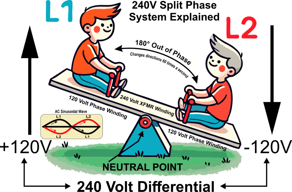
To understand how a 240-volt receptacle works, let’s use the seesaw analogy illustrated above.
Two Hot Wires (L1 and L2)
1. L1 (First Hot Wire):
- Imagine Kid 1 on one end of the seesaw. This kid represents L1, carrying 120 volts.
- Kid 1 goes up and down, representing the alternating current.
2. L2 (Second Hot Wire):
- Imagine Kid 2 on the other end of the seesaw. This kid represents L2, also carrying 120 volts.
- Kid 2 moves in the opposite direction of Kid 1. When Kid 1 is up, Kid 2 is down, and vice versa.
Phase Difference
1. Out of Phase:
- L1 and L2 are 180° out of phase. This means when L1 is at its peak positive voltage, L2 is at its peak negative voltage.
- Think of the seesaw: when Kid 1 is at the highest point, Kid 2 is at the lowest point.
2. Combined Effect:
- The total voltage across the two hot wires is the sum of their voltages. When Kid 1 is at +120 volts and Kid 2 is at -120 volts, the difference is 240 volts.
Electricity Flow at a 240-Volt Receptacle
1. Connected Load:
- When you plug an appliance into a 240-volt receptacle, it connects across the two hot wires (L1 and L2).
- The appliance receives the combined voltage difference of 240 volts.
2. Alternating Current Flow:
- The current flows into the appliance from L1, travels through the appliance, and returns via L2.
- Because L1 and L2 are out of phase, the current alternates back and forth 60 times a second, providing a continuous flow of power to the appliance.
Simplified Summary
- Two Hot Wires: L1 and L2, each carrying 120 volts, but out of phase.
- Alternating Direction: Current changes direction 60 times per second.
- 240 Volts Across the Load: The total voltage difference between L1 and L2 is 240 volts, powering the appliance connected to the receptacle.
Conclusion
By understanding the seesaw analogy and how AC works, it’s easier to grasp how electricity flows at a 240-volt receptacle. The alternating current in the two out-of-phase 120-volt wires creates a combined 240 volts, powering appliances efficiently and effectively.